Industrial Instrumentation Mini Project
Both Thermistors and RTD’s are basically resistors whose resistance varies with temperature.
Thermistors differ from resistance temperature detectors (RTDs) in that the material used in a thermistor is generally a ceramic or polymer, while RTDs use pure metals. The temperature response is also different; RTDs are useful over larger temperature ranges, while thermistors typically achieve a greater precision within a limited temperature range, typically −90 °C to 130 °C.
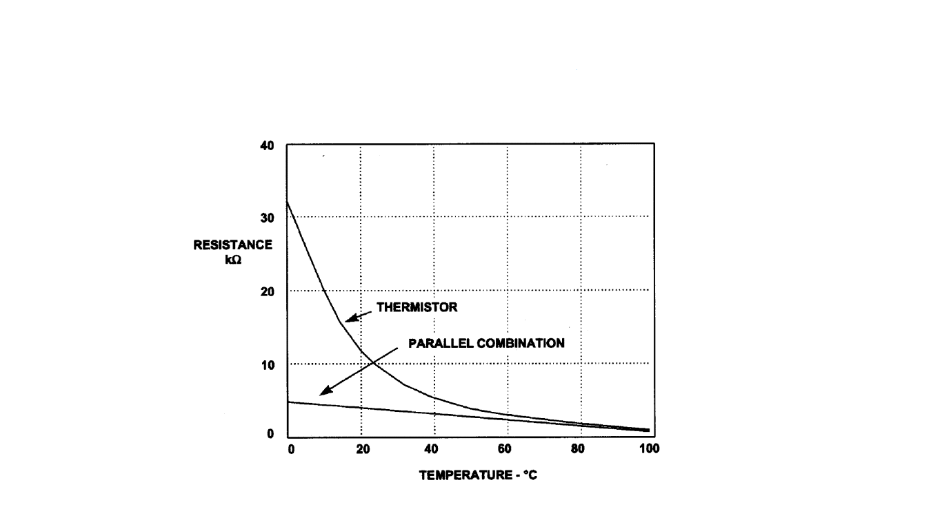
linearization using parallel resistance

So we have high sensitivity and fast response in favor of thermistor, but the non linear behavior is a drawback that we must try to correct.
In tackling this problem the basic approach can be to connect a parallel resistor to the thermistor.

But as you can see above even though this improves the resistance - temperature relationship in terms of linearity, the sensitivity of the thermistor is sacrificed.
Temperature to Period Linearization technique
We will be using a circuit (shown below which functions as a relaxation oscillator) to get a linear relationship between our input variable (Temperature) and output variable (in this circuit it’s the time period).
It is important to note the importance of linearization, we have useful tools used in systems analysis which are applicable to linear systems.
So as it’s much easier to deal mathematically with linear relationships when compared to non linear systems.
Here the output will be a periodic waveform with a time period , here this output waveforms time period is the output variable which is linearised w.r.t. to temperature, unlike the thermistor’s resistance which is non linear w.r.t. to temperature.

Theoretical modeling of T - R characteristics
Now for the modeling of the relationship between the temperature and resistance for the thermistor we can use first order approximation, but this approximation involves assumptions such as carrier mobility’s invariance with temperature etc which are not valid across the entire operating range of the temperature.
Note that for a even more accurate description of the thermistor we use third order approximations like the Steinhart–Hart equation and Becker-Green-Pearson Law which has 3 constants.
Even the original Bosson’s law has 3 constants and is written as
This is approximated to the second order law,
In the above formula’s are constants and stands for temperature while stands for thermistor resistance.
The reason why we go for the 2 constant law rather than the 3 constant law even though the third order approximation fits better is that comparatively its harder to use hardware linearization techniques.1
Also this relationship closely represents an actual thermistor’s behavior over a narrow temperature range.
So if we are going for third order approximations we should use take advantage of the advancements in computing and just obtain a analog voltage proportional to the thermistor resistance, then use ADC to get the digital values which can simply be fed into the 3rd order equation.
Working of the circuit

We should observe the non linearity error is within 0.1K over a range of 30K for this linearization circuit.
Read more from what S.Kaliyugavaradan has written.
References
Written with StackEdit.
The way you integrated various instruments to monitor and control [specific process mentioned] showcased practical application of theoretical concepts.how-to-download-pc-game-free-vpnIt's inspiring to see hands-on projects that bridge the gap between theory and real-world implementation.
ReplyDelete